
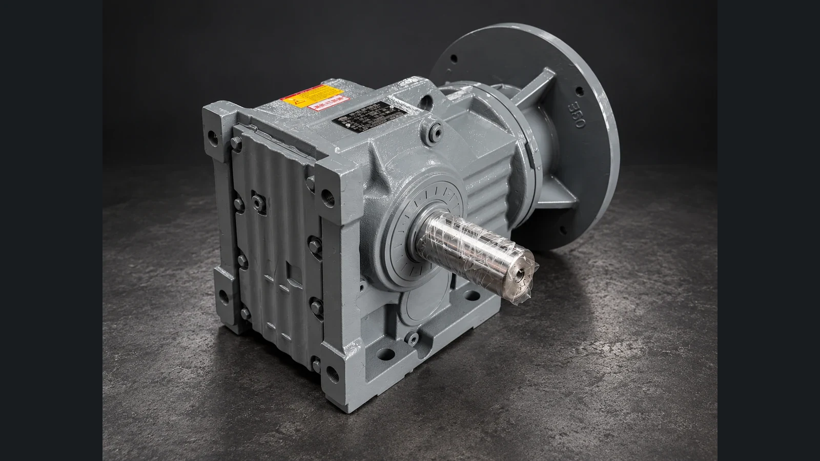
If the nameplate on a gearbox is missing, painted over or corroded, do not guess the model. Record what you can see and measure safely: the gearbox shape, how it is mounted, the shaft connections, the motor nameplate, the input and output speeds and the space around the drive. Then send that evidence with a description of the machine, so the supplier reviews the installation rather than a guessed designation.
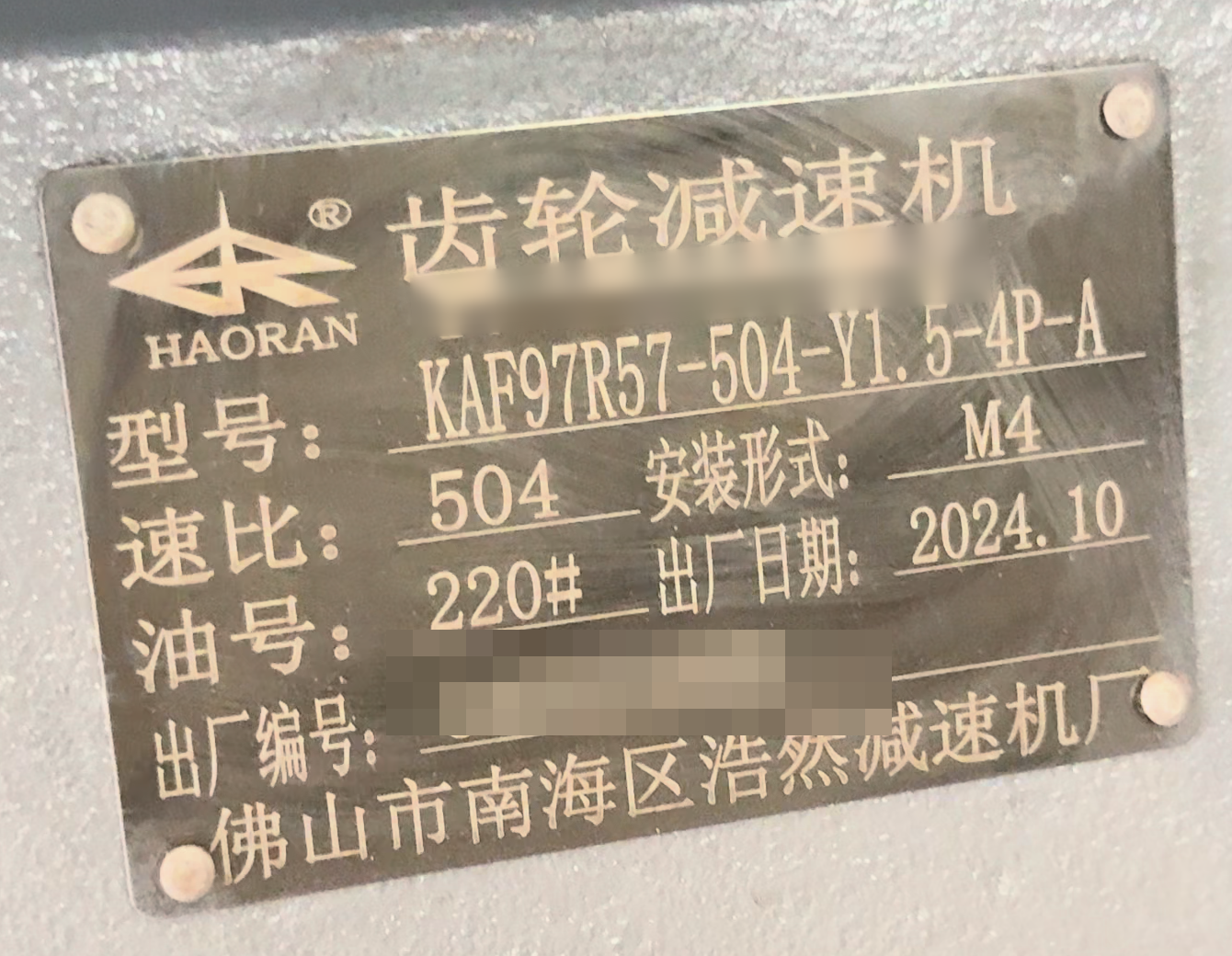
First: how much of the nameplate can you read?
Partly readable. Photograph it anyway. Take a straight-on picture with the plate edges in view, then try another safe angle or better light if reflections hide the markings. Open the image before you send it; if the lettering breaks up when you enlarge it, retake it. Even a partial line of text is useful, so keep the original photograph rather than retyping what you think it says. Use Send your nameplate and say which fields you could not read.
Missing or unreadable. Use the contact page and describe the machine and the drive. Do not fill in the missing designation yourself in order to use a nameplate-based route. The checklist below shows what to include.
Step 1: Note the gearbox type from its shape
The housing shape narrows the search. It does not identify the brand, the exact size or whether another unit will fit.
- Inline (coaxial): the input and output shafts are on the same axis.
- Parallel-shaft: the output shaft is parallel to the input but offset from it.
- Right-angle: the output shaft is at 90° to the input. Helical-bevel and worm designs both fall here and can look similar from the outside.
- Other designs: cycloidal reducers and heavy foot-mounted industrial reducers have their own recognisable housings.
Take one photo from each side if you can do so safely. For a comparison of common families, see R, S, K, F, cycloidal or NMRV: where to start.
Step 2: Record how the drive is mounted and connected
Write down, or photograph from a safe position:
- Mounting: foot-mounted, flange-mounted, or shaft-mounted on the machine shaft with a torque arm.
- Orientation: which way the output shaft points, and where the motor sits relative to the gearbox.
- Output connection: a solid shaft with a key, a hollow bore, or another coupling arrangement.
- Input side: a motor bolted directly to the gearbox, or a separate input shaft driven through a coupling or belt.
A photograph shows the arrangement, but it does not confirm exact shaft dimensions, flange geometry or the positions of the mounting holes. Do not remove guards, approach moving parts or dismantle the drive to get a picture. If a view is hidden, say so in your message and attach an existing drawing if you have one.
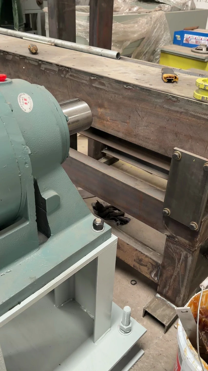
Step 3: Add the measurements you can establish reliably
These dimensions decide whether a replacement can connect to the machine. Record only the ones you can measure safely, with the unit stopped and isolated under your site’s procedures:
| Item | What to record |
|---|---|
| Solid output shaft | Diameter, usable length, key width |
| Hollow output | Bore diameter and keyway |
| Flange | Outside diameter, spigot (pilot) diameter, bolt-circle diameter, number and size of holes |
| Feet | Hole spacing in both directions, hole size, height from the base to the shaft centreline |
| Overall size | Length, width and height of the envelope, plus nearby obstructions |
Write down how each value was obtained (measured, taken from a drawing, estimated). Leave a value blank when it has not been reliably established. A blank is more useful than a guess.
Step 4: Estimate the ratio from measured speeds, without opening the gearbox
The ratio is roughly the gearbox’s own input speed divided by its output speed, both measured under the same operating condition:
ratio ≈ actual gearbox input speed ÷ actual gearbox output speed
- Measure both speeds at the gearbox itself, from a safe position, while the machine runs in one normal condition. You can also work the output speed back from the machine, for example from conveyor belt speed and drum diameter.
- The rated rpm on the motor nameplate is background information only. It is not the gearbox input speed when the motor runs on a variable-frequency drive, through a belt or chain, or through another reduction stage before the gearbox, and even a direct-on-line motor runs at a speed that varies with load.
Arithmetic example only, not product data: a measured input of about 1450 rpm and a measured output of about 29 rpm in the same condition gives a ratio of about 50.
If a speed cannot be measured safely, leave it blank and say so.
Step 5: Use the motor nameplate and the driven machine
The motor nameplate is often still readable when the gearbox plate is not. Photograph it: it shows the motor’s rated power and speed, and it may include frame information. The mounting flange still has to be checked separately from photographs or a drawing. Then describe the machine the drive operates, such as a conveyor, mixer, pump or packaging machine, and how it runs: steady duty, frequent starts or occasional jams.
Motor power alone does not determine a gearbox. The required output speed, the load and the mounting arrangement matter as much, as explained in why motor power alone does not determine a gearbox.
Step 6: Photographs to take
Collect the views you can obtain safely:
- The nameplate, or what is left of it: straight-on, with the plate edges visible.
- The installation: motor, gearbox and driven machine together in one view, including the connection points.
- The shaft connection and mounting: output connection, mounting faces, base or flange, and a view that shows the orientation.
- The surrounding space: clearances and obstructions around the shaft, the motor and the mounting faces.
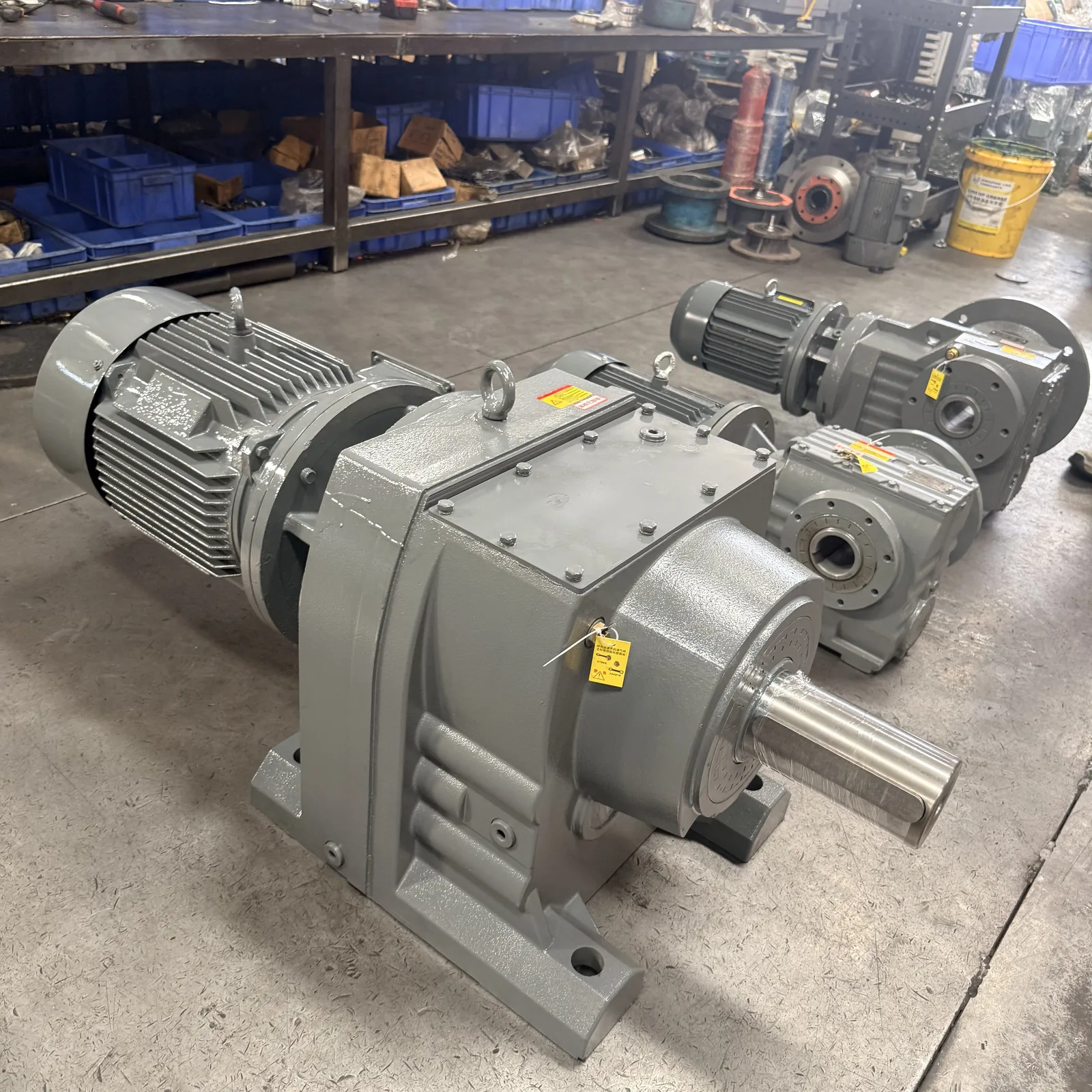
If several views are needed, label each one by what it shows. A tape measure in the frame helps show scale. Do not move equipment or remove guards to complete the set.
What you can expect back
For an installed unit with a readable or partly readable nameplate, the Send your nameplate review replies within one business day. The review looks at the evidence you submitted. It either recommends a gearbox family and mounting arrangement based on that evidence, or names the photos, drawings or measurements still needed, including any interface dimensions that must be checked before quotation. Photographs alone do not confirm dimensions, and the review is not a direct-replacement promise.
When the nameplate is missing or unreadable, contact us with the machine description, the photographs and the measurements you have.
FAQ
Can a gearbox be identified without a nameplate? The housing shape, mounting, shaft connections and speeds usually narrow it down to a gearbox family. A confirmed match still needs reliable measurements of the connection, and sometimes a drawing.
How do I find the gearbox ratio without the nameplate? Divide the actual gearbox input speed by the actual output speed, both measured in the same operating condition. Don’t use the motor’s rated rpm as the input speed, especially with a variable-frequency drive, a belt or chain, or another reduction stage before the gearbox. The result is approximate: it gives a ratio range, not an exact catalogue ratio.
What dimensions are needed for a replacement gearbox? Shaft diameter and key, or hollow-bore diameter and keyway, plus flange or foot dimensions, the height to the shaft centreline and the space around the unit. Leave unknown values blank.
Which photos should I send? The nameplate if any of it survives, the complete installation, the shaft and mounting connection, and the space around the drive.
What if only part of the nameplate is readable? Send the photo anyway through Send your nameplate and say which parts you could not read. Do not fill in missing characters.
If the dimensions match, will a different gearbox fit? Not necessarily. Torque, ratio, orientation, shaft loads and the motor interface also have to be checked against the replacement’s own technical data.
READY FOR A TECHNICAL REVIEW?